Collection: Variable Speed Drive
Frequency converters or also named variable frequency drives are electronic devices that convert a (more or less) fixed frequency and voltage into a variable frequency and voltage. This devices allow electric motors to be operated with a variable speed.
Frequency-controlled drive solutions ensure movement in almost all industries. The huge range of applications contrasts with a large number of drive components. With the help of a few basic explanations and tips for handling frequency converters, you can easily select the optimal drive system for your application in no time at all.
-
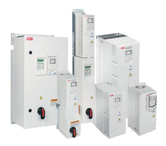
ABB drives for HVAC (ACH580)
Vendor:ABBRegular price From RM1,550.00Regular priceUnit price per -
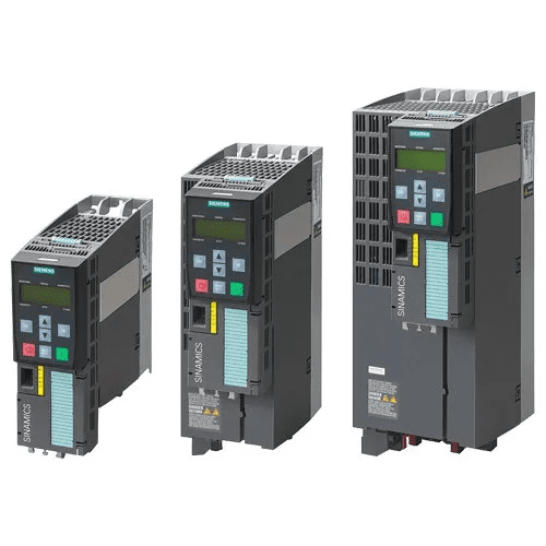
SINAMICS G120P (VSD)
Vendor:SiemensRegular price From RM5,814.00Regular priceUnit price per -
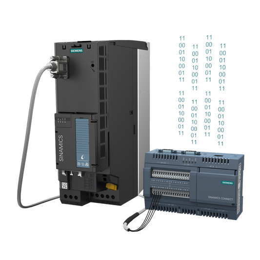
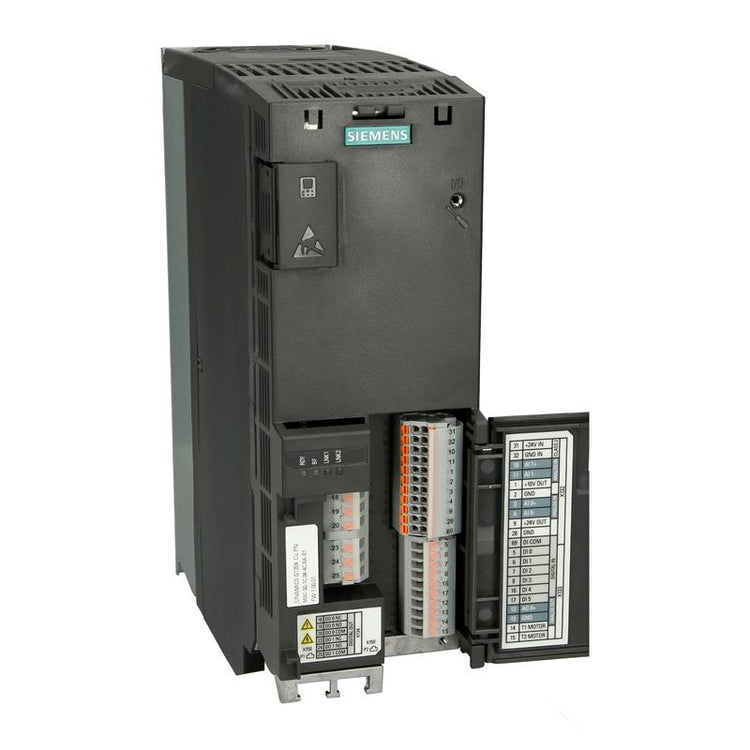
SINAMICS G120X
Vendor:SiemensRegular price From RM2,331.00Regular priceUnit price per -
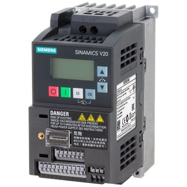
SINAMICS V20, Three Phase
Vendor:SiemensRegular price From RM2,102.00Regular priceUnit price per -
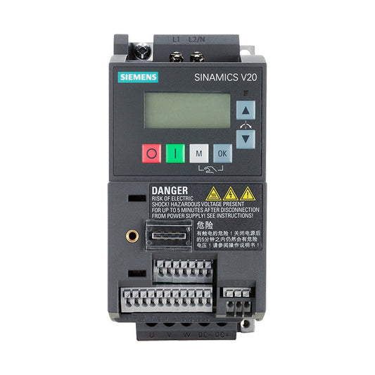
SINAMICS V20, Single Phase
Vendor:SiemensRegular price From RM1,084.00Regular priceUnit price per